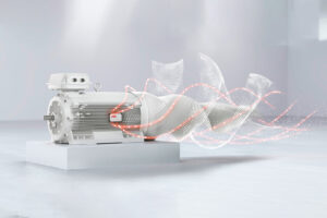
Electricity and magnetism are so closely linked that one can produce the other. An electric current flowing in a cable produces a magnetic field around the cable. A magnetic field moving near a wire causes electricity to flow along the wire. Electromagnetism is the basis of how both generators and electric motors work.
The motor or an electrical motor is a device that has brought about one of the biggest advancements in the fields of engineering and technology ever since the invention of electricity. A motor is nothing but an electro-mechanical device that converts electrical energy to mechanical energy.
The definition of alternator is hidden in the name of this machine itself. An alternator is such a machine which converts mechanical energy from a prime mover to AC electric power at specific voltage and current. It is also known as synchronous generator.
The primary classification of motor or types of motor can be tabulated as shown below, types of motor

The induction motor is an electric motor that uses electric power to induce rotation of the rotor. The main parts of the induction motor and their functions are as follows.
Stator: the stationary part of the motor which surrounds the rotor. The stator consists of copper wires (windings) wound in between the stator’s slots to carry supply current and to induce a rotating magnetic field to interact with the rotor.
Rotor – the rotating core part of the motor fixed to the shaft. The rotor consists of a stack of thin steel laminations and a squirrel-cage construction of conductive bars that react with the magnetic field of the motor and produce torque to turn the shaft.
Shaft – the rotating innermost part of the motor which transmits the rotor’s rotational power to the application fixed to the motor’s D-end.
Bearing – bearings surround the motor’s shaft at both ends and reduce friction between the motor frame and shaft.
Frame – cast-iron or aluminum casing which covers the motor’s core parts and provides electrical connections.


Most of Low Voltage Electric Motor cooling is independent of the direction of rotation, except for certain larger two-pole motors. When the mains supply is connected to stator terminals marked U, V, and W of a three-phase motor and the mains phase sequence is L1, L2, L3, the motor will rotate clockwise, as viewed from the D-end. The direction of rotation can be reversed by interchanging any two of the three conductors connected to a starter switch or motor.
A designation system concerning the method of cooling is based on the standard IEC 60034-6.

Classifications of the degrees of protection provided by enclosures of rotating machines are based on:
→IEC / EN 60034-5 or IEC / EN 60529 for IP code
→IK code acc. to EN 50102 for standard motors. Impact test acc. to IEC 60079-0 for motors in hazardous atmospheres.

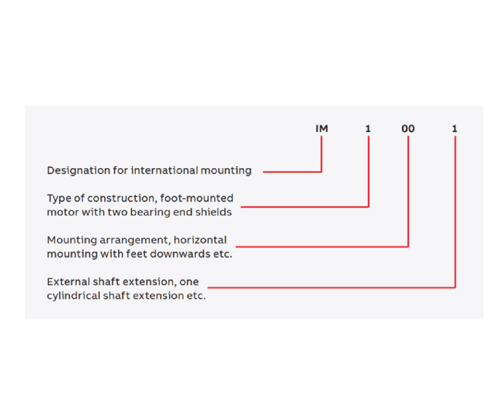
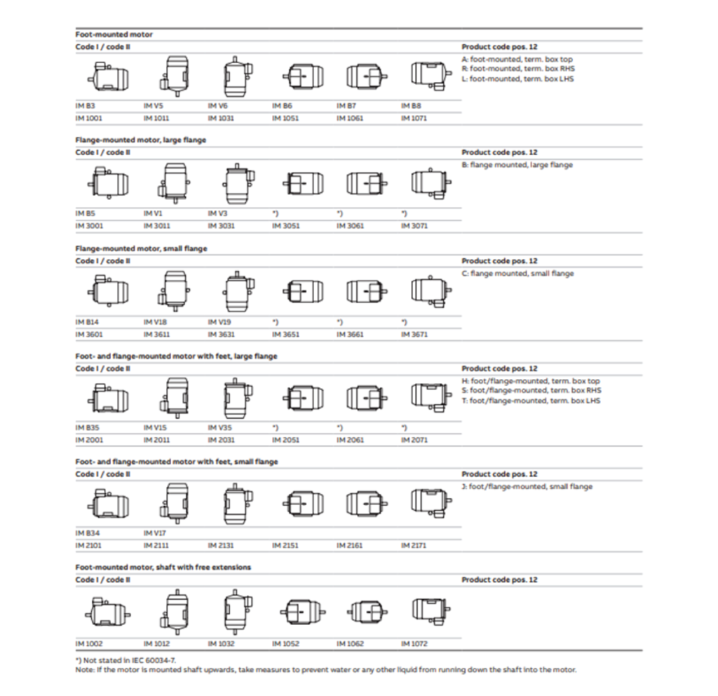
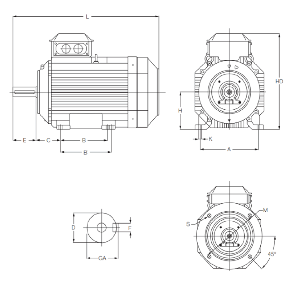


Class F insulation with temperature rise class B, is the most commonly used insulation system for industrial electric motors.
Thermal class 130 (B)
* Nominal ambient temperature 40°C
* Max. permissible temperature rise 80 K
* Hot spot temperature margin 10 K
Thermal class 155 (F)
* Nominal ambient temperature 40°C
* Max. permissible temperature rise 105 K
* Hot spot temperature margin 10 K
Thermal class 180 (H)
* Nominal ambient temperature 40°C
* Max. permissible temperature rise 125 K
* Hot spot temperature margin +15 K


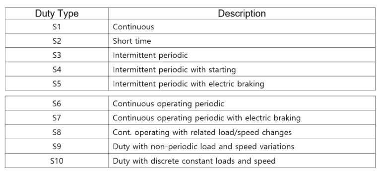
The duty types are indicated by S1…S10 according to IEC 60034-1
